A quick guide to Millers Falls block planes

Millers Falls were one of the last to the party when it came to block planes, their line of planes debuted in Catalog No.40, January 1929. They introduced 21 different block planes in the initial offering, with no real rhyme or reason with the numbering schema used. The planes were all basically carbon-copies of Stanley planes, at least from the perspective of form and function. In reality Millers Falls didn’t do much in the way of introducing anything new, they merely copied the existing Stanley designs, perhaps with some augmentations with respect to knuckle-lever caps etc. Were their planes better than the likes of Stanley or Sargent? No, they just offered a different perspective. Were they cheaper? The No.16 in 1929 was being sold for $2.20, whereas the equivalent Stanley No.9½ sold for exactly the same price.

My guess would be that Millers Falls already had a very successful tool repertoire, and so they figured that producing planes would only enhance their business. Their one interesting plane was the pressed steel No.206 block plane, which didn’t appear until 1940, although it too was a different interpretation of planes like the Sargent No.5206. The table below describes all of Miller Falls block planes, and their major characteristics. Planes are organized based on how they appeared in the original 1929 catalog.

No.LengthYearsAdj.
throat
Depth
blade adj.
Lateral blade
adj.
Bed angleStanley
Ref-No
Notes
166″1929-196520°EF
16C6″1965-197120°Depth adjustment modified to sled-type
177″1929-196420°15EF
266″1929-194420°16Same as No.16 with nickel trim LC
277″1929-194420°17Same as No.17 with nickel trim LC
366″1929-195920°18Same as No.16 but with nickel-plated knuckle-joint lever cap.
377″1929-195920°19Same as No.17 but with nickel-plated knuckle-joint lever cap.
566″1929-196512°60½EF, low-angle
56B6″1965-197612°60½No.56 redesign to accommodate standardized iron.
577″1929-196412°65½EF, low-angle
466″1929-194212°60Same as No.56 but with nickel trim
477″1929-194812°65Same as No.57 but with but with nickel-plated knuckle-joint lever cap. Also Craftsman No.3732.
666″1929-194412°61Same as No.46 but with non-adjustable throat, rosewood knob
077″1929-197020°140rabbet plane (skewed), EF body, rosewood knob, polished nickel trim
555½”1929-196020°103EF, screw cap clamp
977″1929-196020°120Longer, and wider than No.55, EF, rosewood knob
757″1929-196520°220longer and wider than No.45, EF, rosewood knob
75B7″1965-196820°220No.75 redesign to accommodate standardized iron. Sold as Fulton No.5257/3701; Dunlap No.3701.
75-01B7″1968-1980s20°220Catalog re-organization.
455½”1929-196420°203smaller version of No.75, EF, rosewood knob
33½”1929-197445°100No.33 with a curved handle, EF
333½”1929-197445°101EF, later gray/red
55½”1929-196420°102EF
877″1929-196420°110EF, rosewood knob
688″1929-196120°130double-end block plane (one end rabbet), EF, rosewood knob
7007″1931-196420°1247Also Shelburne No.700 M-S
2066¼”1940-195920°pressed steel construction
206B6¼”1959-197012°Same as No.206 with 12° bed.
7077″1956-197420°1247EF, red LC, grey body, hardwood knob
14556″1956-197412°61No.66 reborn. EF, rosewood knob. No.1455B, redesign to accommodate standardized iron.
84556″1974-197712°61All black.
87077″1974-1990s20°1247re-numbered No.707
97757″1969-197120°Teflon-coated No.75
90333½”1974-1990s20/45°H101pressed-steel construction
EF = enamelled black finish; LC = lever cap; ORANGE=not originating in 1929

For a much deeper dive into the intricacies of Millers Falls planes, check out Millers Falls Planes.

Birdsill Holly – the first metal block plane

Many people likely think the first true metal block plane was the Stanley No.9½, which appeared in 1872, but it wasn’t the first block plane. The first cast iron plane produced in North America was that of Hazard Knowles, in 1827. The first cast iron block planes were actually produced by Birdsill Holly in the 1850s. Born in 1820 in Auburn NY, at the age of 10 Birdsill Holly first apprenticed to a cabinetmaker, then a machinist. Although only having a 3rd grade education, Holly was a natural inventor. In 1848 together with Horace C. Silsby and Washburn Race Holly formed the company Silsby, Race & Holly Co. located in Seneca Falls NY. There he was the visionary behind the manufacture of hydraulic machinery and steam-powered fire engines.

The bench plane from Birdsill Holly‘s patent (US9,094)

The planes produced by Holly were very interesting, but honestly they seemed like a bit of a sideline because the company did not manufacture the planes for very long, only 1852-1859. In 1852 Holly received a patent (No.9094) for a “Hand-plane”, with improvements to metal hand planes, and began producing planes. The bench planes had a novel design with the base basically in the form of a flat iron. Instead of the blade being held in the plane by a wooden wedge, this new design used a metal sleeve with a locking screw. The underside of the sole in these bench planes sometimes incorporated relief holes to reduce friction, and other times offset corrugations, one of the first manufactures to incorporate this technology.

The bench planes were followed by what is arguably the first true metal block plane. The block plane had a tapered, boat-like shape, with a “shoebuckle” lever cap design. The lever cap essentially had cutouts in it, and pivots on the same type of metal rod found in simple block planes. A metal wedge or pin made or cast iron or brass would be slid in to hold the cutter down. Later versions had a brass screw cap to lock the lever cap against the cutter. There are very few of these block planes, and likely they were never commercially manufactured. However the plane design did contribute heavily to the development of the Stanley No.110 block plane, one of Stanley’s earliest designs. The 110 was essentially a complete rip-off of the Holly’s plane, but was completely legal as Holly has never patented the design. The other amazing thing about this block plane is that fact that it had 15° bed angle.

The Holly block plane

In 1859, around the time plane manufacturing ended, Holly created his own company, Holly Manufacturing Company in Lockport NY, where he worked on fire protection systems. In 1877 Holly formed Holly Steam Combination Company, working on a steam heating system. By the end of his life in 1894 Holly had amassed more than 150 patents. These block planes, if you are fortunate enough to find one, sell for upwards of US$1000 these days.

What steel was used in vintage plane blades?

Modern planes come blades made of exotic types of steel, but what about vintage planes? For instance, what sort of steel did the Stanley’s use?

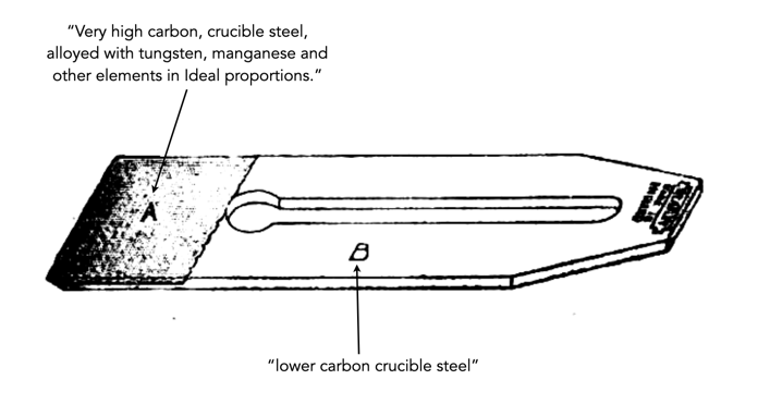
The short brochure “Read this before you use STANLEY PLANES”, describes the blades. It appears that for several generations the steel used In Stanley Plane Cutters was made for Stanley in one of the steel mills in Sheffield, England and was known as “Composite” Steel. It was comprised of a cutting edge of “very high carbon, crucible steel, alloyed with tungsten, manganese and other elements in ideal proportions”, and a softer backer made of lower carbon crucible steel. Both were welded together when cast, and made of the best quality Swedish pig iron.

A Stanley composite steel blade

It is hard to know exactly how long Stanley made these composite blades. There is no mention of composite steel in the 1906 Stanley catalog, just “English Steel”. Examining the various catalogs over the years, it is not until No.129 published in 1929 that there is any mention of composite steel. In Catalog No.34 (1915) it describes the use of “the finest quality English steel”, and by Catalog No.34 (1942) is had changed made in Sheffield, England from “the very best grade of Swedish iron”.

Sargent planes of the VBM type, short for Very Best Made, had blades made of the Very Best Tool Steel, whatever that seems to mean (it was a phrase used by many tool companies). Union planes were made out of “a superior grade of heavy steel”. A 1939 catalog from Swedish company E.A.Berg talks about “best quality Swedish steel”, compound-steel, and “Swedish Charcoal Steel”, but fails to discuss specifics. Maybe it was a proprietary blend, or perhaps they just felt that people wouldn’t be interested in the “chemistry” side of things.

Record took great effort to make sure its blade steel was special.

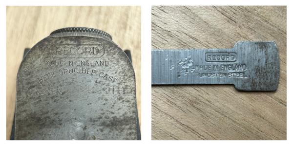
Record made it well known that their blades were made using Tungsten steel. The concept is explained in Planecraft, first published in 1934. The tungsten combines with carbon to form tungsten carbide, a metal used in machine tools for high speed cutting of metals. Basically “a plane iron containing the correct amount of Tungsten is harder and more resistant to wear, and will take a keener cutting edge, and hold it for a longer period than would an ordinary steel.“. The tungsten also helps create a very small grain size, making a blade more resistant to shock.

Why did so much of the blade steel seem to come from Sweden? Swedish iron ore deposits contain small percentages of the element vanadium, which makes steel produced from it a natural alloy. The presence of vanadium allows production of a tough, fine-grained steel whose high tensile strength is not crippled by brittleness.

Why are there no wooden block planes?

The modern metal block plane was an artefact of the Victorian period. I mean different types of small metal planes did exist before then, like the British chariot plane, but they did not evolve from some wooden plane forerunner. The size of wooden planes has always been limited by the material they were made of – wood. Small wooden planes can be constructed, but their function would be constrained by the natural limitations of the wood. This is the reason why you won’t see many wooden block planes, even in places where wooden planes are quite common, e.g. Germany. Note that the discussion here is focused on a wooden equivalent of a traditional block plane with a bed angle of 12° or 20°.

One of the main reasons for the lack of wooden block planes lies in their construction. Wooden planes typically use a bevel-down blade configuration. In a bevel-down plane, the blade typically rests on a 45° wooden bed. Because the bevel sits behind the edge, the cutting angle is fixed at 45°, even though the bevel on the blade could be 25°. This is not a great angle for planing end-grain with a block plane. Bevel-down planes have limits to their bed angles (ca. 35°) before clearance becomes a real issue. Block planes, on the whole use a bevel-up configuration. In a typical low-angle metal block plane, the blade is bevel-up, where the bevel leads into the cut, contributing to the cutting angle. If the bed is low, typically 12°, the effective cutting angle becomes 37° once the blade angle of 25° is factored in (a much better angle for end grain). The bevel-up design was introduced to lower the bed-angle in order to make end-grain planing easier, because it minimizes tearing end-grain. A “normal” metal block plane with a bed of 20° + 25° blade will create a 45° cutting angle.

Fig.1: Bevel-down versus bevel-up

Now, it is possible to have low angled bed in a metal plane because the integrity of the metal body structure allows it. For example the precursor to the block plane, the metal chariot plane often had bed angles of 12-16°. However it is almost impossible to reproduce low bed angles in most woods, due to the tenuous nature of the material – therefore it is nigh impossible to have a wooden bevel-up block plane. Figure 2 shows a mock-up of a wooden block plane with a normal 20° bed, and explains some of the structural issues. In the tool epitome Antique Woodworking Tools, by David R. Russell, there are two planes (a late 19th C. chariot plane and an 1830’s mitre plane), both made of boxwood that have pitch’s of 21° and 20° respectively. The caveat is that both are reinforced with metal near the mouth of the plane.

Fig.2: A cross-section of a low-angle block plane (with a 20° bed) constructed of wood. The plane cheeks would become quite fragile, and subject it to splitting due to the wedging forces required to secure the blade. The bed near the plane mouth would also be quite weak.

If you look through one of the older E. C. Emmerich catalogues (1930-1950s) from Germany, there is little or no mention of a wooden block plane. At some point one did appear in the catalog, and is still made today, the 649-P Pocket plane. It is likely one of the few modern attempts at a wooden block plane, and is unique in that it’s blade is bedded at 50º (York pitch), ideally suited to hardwoods. But the lack of low-angle block planes in Germany meant that American-style metal block planes were utilized from early on (this may have been why Kunz, was so successful in manufacturing metal planes in Germany).

Wood, a poem

Behold the wood
where life has drawn
lengthwise a river
crosswise an island, surrounded
by concentric years.
Behold the darkening knots
like shadows of birds’ eggs
in nests that have tumbled
from living towers that have fallen.

Harry Martinson (Swedish poet, 1904-1978)

Were dovetails used on historic English chests?

When woodworkers build modern chests, they often use dovetails, and let’s face it – dovetails are extremely strong for this purpose, and they may be the most aesthetically pleasing of all the joints. But what about historic chests? In Ancient Coffers and Cupboards, [3] Fred Roe looks at how these were built from “the dark ages” until the 16th century. The coffer was a box of great strength, intended for the keeping and transporting weighty articles – essentially a strongbox, or small chest. Roe’s book contains numerous illustrations of these coffers over the ages, many ornately decorated. But how were these ancient chests held together? Were they festooned with dovetails?

The simple answer is probably not, or rather we don’t know.

As we know, the ancient Egyptians were already using dovetails in high-end carpentry. There is evidence from the Roman architect Vitruvius, in his Ten Books of Architecture (25BC) on the construction methods for roof beams, including the use of “dove-tailed tenons”. So it is possible that these methods were used in Roman Britain. But while we have this information, it’s a gargantuan leap from the ancient world to the more widespread use of dovetails in England starting circa 1600. Were the “Dark Ages” so dark woodworking didn’t evolve? We do know that much of the technology introduced by the Romans in Britain was lost in the years after their decampment. There is some evidence of the existence of dovetailed chests in England from early times. A monk present when the tomb of St Cuthbert (who died 687, but was reburied numerous times) was opened in 1104 observed that one of the chests containing the remains was “joined and united by the toothed tenons of the boards which come from this side and from that to meet one another, and by long iron nails” [2].

Fig.1: Dovetail joint from [3]

In Old Oak Furniture, also by Fred Roe [4], he talks about chests during the Gothic period (12th C-mid 16th C)- “they were always fastened together with wooden pegs or trenails, iron only being used for hinges, clamps, and locks.”. He goes on to say that dovetailing when practised at all, in the 13th and 14th centuries was done so in a secret form – it was carried out in a singular manner, being worked perpendicularly down the inner part of the uprights (stiles), so as to be invisible from the front (see Figure 1). This is basically a vertical sliding dovetail, with curved dovetails, seemingly a lot of work for a joint that was hidden (never mind the curves!). A series of small fan-tailed mortises interlocking with each other at the corners may be sometimes seen on late Gothic coffers, such as that in the church at Evesham [4] (see Figure 2). In England it was unlikely this form of dovetailing was practised before the start of the 16th century.

Fig.2: Visible dovetail joint ca. 16th century [4, p.137]

There is an excellent example of a barber-surgeon’s chest from the wreck of Tudor ship Mary Rose which sank on July 19th, 1545. Constructed of walnut, it has multiple dovetailed corners reinforced with nails. Other dovetailed chests were constructed of elm, oak, walnut and poplar. What is interesting here is that most of the chests on board the Mary Rose were of boarded construction, either butted or rebated and either nailed or pegged together [1]. During this period, dovetail construction was generally the purvey of continental furniture. Author David Knell makes the point that dovetail chests were imported into into England from places such as Germany and northern Italy during the Tudor and early Stuart period, although he also points out that there is no evidence the chests weren’t made in England (perhaps by immigrant craftsmen) [1].

The reality is that we really don’t know much about the history or evolution of dovetails. Was the English dovetail an offshoot of the sliding dovetail used in making early chests or did it evolve from the use of dovetails in English house construction? Was it integrated into British woodworking from the woodworking practices of immigrants craftspeople from the continent? A large scale study of the history of woodworking joints has never been undertaken. The only way to begin to understand the history of dovetails would be to investigate furniture joints throughout history. This doesn’t really tell us how or why, but it would give a picture of when. But it is also fraught with issues related to finding wooden furniture pieces from relevant periods.

Regardless of all these unknowns, the use of dovetails from 1600 onward had repercussions in the cabinetmaking industry. For instance the mortise and tenon joints used in building carcasses required lumber to be a minimum of 25mm thick, whereas dovetails would reduce this, likely to something more like 18mm. By the late 17th century, dovetails were a common feature in drawers, and by the mid 1700s, the broad dovetails sometimes hidden by mouldings had narrowed into finer ones.

P.S. The German word for a dovetail joint is Schwalbenschwanzverbindung, quite a tongue-twister! It is actually the German for a swallowtail joint, as on the continent there are various names including culvertail and fantail joint.

References

  1. David Knell, “Tudor Furniture from the Mary Rose“, Regional Furniture, XI, pp.61-79 (1997)
  2. Penelope Eames, Furniture in England France and the Netherlands from the Twelfth to the Fifteenth century, Furniture History Society (1977)
  3. Fred Roe, Ancient Coffers and Cupboards Their History and Description from the Earliest Times to the Middle of the Sixteenth Century, Methuen & Co. (London) 1902
  4. Fred Roe, Old Oak Furniture, Methuen & Co. (London) 1905

Japanese versus Western saws

Here is a summary of the pros and cons of Japanese versus Western saws. This is not to say “one is better than the other” but just provide a side-by-side comparison of the features of each.

CharacteristicJapanese sawWestern saw
Kerf
(slit made by cutting)
Thin – removes less wood, requires less effort. Some model making saws have a kerf as small as 0.1mm.Thick – removes more wood, and requires more effort.
Crosscut: 1.1 – 1.5mm
Rip: 1.3 – 1.8mm
Blade thickness
(average)
typically 0.2 – 0.8mm
An average 0.3mm blade will produce a kerf of 0.4-0.5mm.
dovetail / tenon: 0.46mm / 0.64mm
panel: 0.8 – 0.9mm
CostReplaceable-blade saws are generally inexpensive. Hand-made, higher-end artisan saws are very expensive.Good quality new or restored saws can be expensive.
SetupThey are ready to use straight out of the box, no sharpening required.Artisan-made saws are generally ready to use out of the box, others may need some fine-tuning.
Low-endLow-quality saws are generally quite usable.Low-quality saws are often poorly sharpened and can be frustrating to use.
Tooth hardnessGenerally teeth are hard – RC 51-58 (handmade), 61+ machine-made, impulse hardened. Sharper, but more brittle. e.g. Gyokucho saws are RC67.The teeth are generally softer, and require more frequent sharpening. Hardness is typically around RC 52-54.
Crosscut robustnessCrosscut teeth are delicate. It is possible to lose a tooth in circumstances such as tough wood, or hidden knots.Crosscut teeth are robust, much harder to damage.
SharpeningReplacement blades are impossible to resharpen. Handmade saws need to go back to Japan to to a qualified sharpener.Teeth can be resharpened many times (by the user). The resharpening can be done inexpensively.
Blade robustnessSaws are easy to damage (if improperly used), because the blade is so thin, it is easy to bend on the return stroke if the saw isn’t properly aligned or tensioned.Blades are much thicker and unlikely to buckle in use. The teeth are more durable than Japanese saws, and unlikely to break.
Dimensioning lumberJapanese saws made for dimensioning lumber have much shorter blades than their western counterparts and therefore might require more effort (stroke) to do the same work.Western saws for dimensioning lumber are larger, and have longer blades. Less effort to do the same work.
Bench useJapanese saws are designed to be used on low benches. As such they are not as effective in all circumstances.Western saws are designed to be used using saw benches, or similar, 2+ feet off the ground.
SawdustPulls sawdust back towards the cut, and the sawyer.Pushes sawdust away from the cut.
VintageVintage saws are expensive, and not always functional.Vintage saws are plentiful and inexpensive, however they do require learning how to restore and sharpen.
WeightJapanese saws are generally designed to be lighter. A thinner blade and a handle made of softwood.Western saws have thicker blades, and larger handles, made of hardwoods, so the saw is heavier.
Blade lifespanA good replaceable blade will last around 2 years, depending on use. Some blades last a long time.Blades will last a lifetime with proper sharpening.
Teeth-per-inchCrosscut: 14-30
Rip: 9-10
Crosscut: 6-10
Rip: 4-7
Dovetail: 14-20
UsabilityRequires the use of Japanese postures, and holding techniques for work.
Generally two-handed use. Requires some finesse due to the thinness of the blades.
Large cuts do require some experience, due to the smaller size of the blades.
Classic western postures, use of saw-horses etc. Mostly used one-handed.
May be less prone to errors for the novice woodworker. Large cuts are easier due to large size of panel saws.
SustainabilityBlades are disposable, but can be transformed into scrapers.High level of sustainability for a well maintained blade.

Did the ancient Egyptian’s use dovetails?

Dovetails are likely the most talked about woodworking joint. They are interesting because they exist in both metal and wood working realms. In metalworking they are mostly used in scenarios like joining the sides to the sole of infill planes. Many people seem to think that they have only been around since the mid-1800s, but they have been around for much longer. There is evidence from surviving pieces of furniture entombed with mummies that the ancient Egyptian’s used dovetails. This is hardly surprising, wood furniture would have been the purvey of the rich, as wood would have been scarce, and expensive if imported.

It has been suggested that a “dovetail mitre housing” came into use in the period from the Third to the Fifth Dynasty (ca. 2670-mid 24th century BC) [1]. The true dovetail has no exact date, but it is suggested that by the 12th Dynasty (ca. 1991–1778 BC) “double-ended dovetail dowels were inserted to joins planks end-to-end, that is pieces of wood tapering like a wedge from each end into a waist at the centre inserted in correspondingly shaped recesses” [1]. An exceptional example of dove-tailing is a gable-topped linen chest from the New Kingdom, 1492–1473 B.C. (see Figure 1). Each end board in the chest has three small tails per side, with the side-boards using with two long pins in between the tails. The boards are 1cm thick, and the entire chest is only 69.5cm (L) by 36cm (W) by 44cm in size.

Fig.1: Gable-topped linen chest from the New Kingdom (The MET)

None of this explains whether the Egyptians originated the use of dovetails, or adapted them from another culture. What is certain is that “flat” dovetails were used in both Egyptian ship-building, and masonry. During the New Kingdom the stones used in constructing monuments were often kept close together using dovetails [2], what we would today call a butterfly joint used to prevent wood splitting.

We know about Egyptian woodworking because of the preserved artifacts. Egypt had a dry climate, and because these types of artifacts were often buried with the people that owned them, they were well preserved in tombs which lay undisturbed for thousands of years. In other ancient cultures such as Greece, there is less woodwork, due to both climate, warfare, and differing belief with respect to burials (our knowledge of Greek furniture is derived almost entirely from paintings and sculptures). Coffins actually tell us a lot about ancient Egyptian woodworking, at least from the perspective of joints: plain butt joints, mitre joints secured by dowels, shoulder-mitres and double shoulder-mitres, dovetails, dovetail-mitre-housings and halving joints.

References

  1. Eric Marx, “Ancient Egyptian Woodworking”, Antiquity, 20, pp.127-133 (1946)
  2. Demortier, Guy, “Revisiting the construction of the Egyptian pyramids.” Europhysics News, 40(1) pp.27-31 (2009)

Exploring Japanese saws (iv) – saw makers

Trying to decipher the various saw provided by manufacturers can be challenging. Some stores carry a particular brand, but perhaps not all the saws made by that manufacturer. This post just provides a bit of information on the different saw makers, taking some of the mystery out of who is making saws. A future post will outline the saws produced by Gyokucho, Nakaya, and Zetsaw. I have chosen these because of the broad range of saws they offer.

Most replacement-blade saws are very similar. They may differ slightly in their teeth configuration, or shape, but structurally the saws are the same. Where they do differ is the type of collar used to connect the blade to the handle.

Replacement-blade saws:

Gyokucho: Gyokucho saws are made by Razorsaw Manufacturing who have been making hand saws with replaceable blades since 1969. It is said that Gyokucho invented the first replaceable blade saws. They have a long history of selling saws in the west. Gyokucho make saws for many different purposes, e.g. tree pruning, reciprocating saws.

Nakaya: The history of Nakaya dates back to 1907, when it was founded by Nitaro Nakaya in Hokkaido. In 1967 they produced the first automated saw cutting machine, and still sell saw manufacturing equipment. It was not until 1980 that they developed handsaws for export. Today they produce a wide range of handsaws for woodworking, arborist work, and even a frame saw with a Japanese blade.

Zetsaw: The Zetsaw brand of saws is made by Okada Hardware Mfg. Co. Ltd. located in Miki, Japan. They have been producing tools since 1943, and were the first company in Japan to introduce impulse-hardening treatment to improve tooth hardness. The brand is commonly known as “Z-saw”.

Suizan: The Suizan brand has over 100 years of tool making history. They make saws and hand planes. It seems as though the company concentrated on the export market, and is sold in over 30 countries. The tools are made in Tsubame Sanjo, Niigata Prefecture.

Bakuma: Founded in 1945, in Hayashi-cho, Sanjo City, Bakuma began manufacturing nail-pullers (crow-bars). They started production of replaceable-blade saws in 1989. Apart from saws they manufacture an equipment for houses, e.g. ventilation fans. They manufacture a reasonable number of saws.

Other: There are also companies that make specialist saws like the Yoshiwaka D-keep, which is a Dozuki saw which has a depth adjustment mechanism.

Traditional (artisan) saws:

Possibly the most prominent traditional saw maker is Hishika. In addition there are saws made by small-scale artisans: Shirai Sangyo (Sanjo), Daizo Mitsukawa, and Shinsui Nakaya (Sanjo).

Hishika Industries: Made in Miki in Hyogo prefecture, Hishika saws are handmade by craftsmen using traditional techniques for hand hardening and tempering, distortion removal, and polishing. The saws are made with very thin steel, and designed in such a manner that the saws can be resharpened. They produce saws for general lumber cutting, woodworking, pruning saws for gardening, and fine saws for making musical instruments. These saws are not for the beginner. For the model maker, they have a super-fine cut saw with a kerf of 0.1mm. You can watch a series of videos on how the artisans at Hishika create saws here.

The different saw collars used with replacement saw brands (and Hishika)

Dovetail characteristics circa 1900

We talk a lot about dovetails these days, but how were they perceived over a century ago? Paul Hasluck, in “The Cabinet Worker’s Handybook” (1907) describes dovetailing as “the most general form of jointing in cabinet work”. Yet while Hasluck describes the process, even mentioning puzzle and round-cornered dovetailing, he doesn’t go into specifics.

Fig.1: Examples of dovetails from The Cabinet Worker’s Handybook.

Below is a description on dovetail proportions and angles from a 1910 book “Modern Cabinetwork: Furniture and Fitments“, by Percy A. Wells, and John Hooper. The authors were from the Shoreditch Technical Institute, which would become the London College of Furniture.

  • Setting out Dovetails − The ratio between dovetail and pin varies according to the work in hand. Thus, in draw work, the pins are very narrow, and the dovetail large (Figure 3a). This makes a strong joint, and is not unsightly or cumbersome. Carcass dovetails that are concealed by plinth or cornice have the pins cut larger, the ratio of pin and dovetail being 1:3 (Figure 3b). Cistern dovetailing required to resist the heat generated when soldering the lead lining, have both pin and dovetail equal, any shrinkage which may then occur is evenly distributed throughout the whole case (Figure 3c).
  • Angle of Dovetails − The angle for cutting dovetails to obtain the maximum amount of strength from the joint may be either 1 in 6 (9.5°) or 1 in 8 (7.1°). It will be found advantageous to cut exterior dovetailing, such as drawers, instrument cases etc. where they must have a neat appearance, 1 in 8, and the heavier types of carcasses, bases, and chests, 1 in 6.

Many woodworking instruction books of the period did not specify an angle as such, or suggested that the angle of the sides of the “tail” should not exceed about 15°, for hardwoods a little more, and soft, weak woods as little as 10° [1] (note that many older texts specified angle from 75-80°, see the Figure 2). A 1 in 4 dovetail has an angle of about 14°.

Fig.2: Different ways that dovetail angles are expressed
Fig.3: Different dovetail spacing
  1. Bernard Edward Jones, Every Boy his Own Mechanic (1919)