The depth adjustment mechanism of Chaplin

Unique amongst block planes is the blade depth adjustment mechanism cited in Chaplin’s Patent No.126,519, and used by Tower and Lyon in their planes. The patent was for a bench plane, but the basic principles were adapted for the block planes.

The blade depth adjustment mechanism is based on the use of a saddle, or rest plate, upon which the blade rests, and is clamped to by the lever cap. The saddle is secured to the plane body using a single screw which still allows it to move in a longitudinal manner. Note the saddles of the No.15 and No.30 in Fig.1 are different – the No.15 has a recessed centre, with what seems like a hand-stippled bed. The surface of the No.30 is flat, with the exception of the recess for the securing screw.

chaplin_saddles

Fig.1: The saddle of the adjustment mechanism

Depth adjustment is achieved by an ingenious adaptation of the worm and worm-wheel gear system. It consists of a paddle-type lever attached to a section of worm gear (screw threads), the thread of which activates a partial worm wheel (quasi half-nut) formed in the underside of the saddle.

chaplin15_worm2s

Fig.2: Parts of the depth adjustment mechanism

The worm gear, and partial worm wheel are shown below in Fig.3.

worm_mechanism2

Fig.3: Worm gear and worm wheel

When the paddle is moved from right-to-left, the blade is forced outward, and when the paddle is moved from left-to-right, the blade is drawn in. The saddle, and hence the blade have a total movement of approximately 1/8″.

worm_mechanism1

Fig.4: Lowering vs. raising the blade

The clasping mechanism to attach the lever cap to the blade, and saddle is also unique to these planes. The lever cap has two lugs projecting downwards and terminating in hooks. The saddle is designed in such a manner that is has a shoulder on either side, against which the lugs on the lever cap strike.

chaplin_levercap

Fig.5: Lever cap and blade (left), mechanism in place (right)

The lever cap is attached to the plane by sliding it into the blade and saddle attached to the boss (the frog-like entity that protrudes from the stock). When the thumb screw is operated, the blade is forced down upon the upper portion of the saddle, forcing the worm gear-wheel system to engage. This holds both the blade and saddle rigidly is place (Fig.5).

The bench planes produced by Tower & Lyon were more prominent than their block planes, but that being said it is hard to find much relevant information. There is a Tower & Lyon catalog (in reprint form), but this is 1904, likely already containing some of their “improved” planes based on a 1902 patent related to an improved design for block (No.716,386). A type study and more information on Chaplin’s Patent Planes can be found on this site provided by Peter McBride.

Plane body finish removal – Soy Gel

When restoring old planes, sometimes the finish is too far gone to save. It could be that there is less than 50% finish left, or paint is flaking. At some point a decision must be made as to whether or not to strip the finish off, and reapply a new finish. I don’t like highly-toxic paint removal remedies, so I bought some Soy-Gel.  I used it previously to remove paint from an old industrial light fixture, and it worked extremely well – how well will it work on a plane?

Soy-Gel is made of 100% soybeans. It will supposedly remove oil and water-based coatings, acrylics, latex, enamel, urethanes, and two-part epoxies. If there is paint containing lead, then the gel actually encapsulates the lead flakes in the gel. There is also no odour. Now Soy-Gel is by no means made completely of soybeans – the active ingredient is N-methyl pyrrolidone, which is common in many of the “low toxic” paint removers – however it is biodegradable.

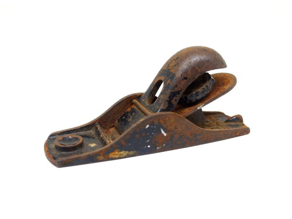
To test the viability of using Soy-Gel, I used an old Stanley No.102 block plane, covered with old flaking paint, both on the body and the lever cap.

stanley102before

Fig 1: The Stanley 102 before paint removal

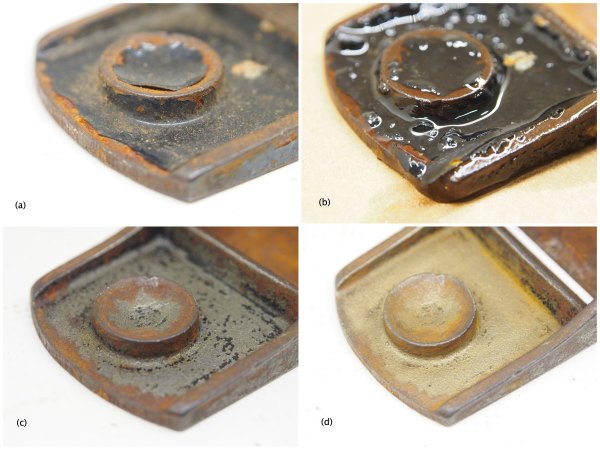
Figures 2 and 3 outline the process of paint removal on the toe (Fig.2), and heel (Fig.3) of the plane. I applied a thick coating of the gel on the plane body and left it for 18 hours, after which I cleaned off the gel with a wooden scraper, and washed the residue off. There was still some residual paint left in the crevices of the plane (mostly the markings on the body). Figs 2(c) and 3(c) show the plane after the first application of gel. I applied a second thinner layer of gel to remove any residual paint, and left it overnight.

soy_102part1

Fig.2: Plane toe – (a) Original finish, (b) Gel applied, (c) Finish removed, and (d) Surface brushed with brass brush

After about 10 hours, I cleaned the plane body again and used a scouring pad to remove the final specks of paint. The plane cleaned up nicely, and can be prepped further with a brass brush.

soy_102part2

Fig.3: Plane heel – (a) Original finish, (b) Gel applied, (c) Finish removed, and (d) Surface brushed with brass brush

The Soy-Gel did a really good job in removing the paint from the plane, with no real mess involved. The gel sits nicely on vertical surfaces, and is able to penetrate the smallest crevices. Note that it does not effect any rust present on the plane – so this plane will need to be dunked into Evapo-Rust, and then wire-brushed before re-finishing. At the end of the day, it’s not a perfect “green” solution for paint removal – but it works extremely well. At some point I’ll see how well it works on an older finish, i.e. japanning.

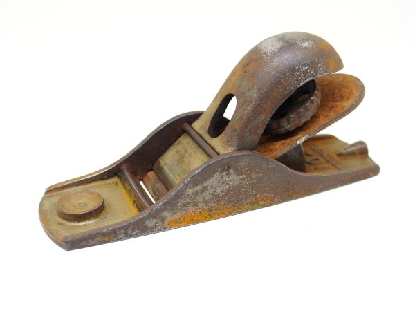
stanley102after

Fig.4: Stanley 102 after paint removal


The block planes of Tower and Lyon (aka Chaplin)

In my collection I have two block planes from Tower & Lyon (New York, 1884-1916) – Tower & Lyon were a hardware manufacturer which manufactured the planes based on a patent obtained by Orril R. Chaplin in 1872 (No.126,519). Tower & Lyon offered a number of basic models of block plane:

No.0, model makers, L=5″, BW=1-1/8″
No.15, fixed throat, japanned, L=6½”, BW=1-7/8″ (corrugated top, pierced lever cap)
No.18, fixed throat, nickel-plated, L=6½”, BW=1-7/8″
No.20, adj throat, japanned, L=6½”, BW=1-7/8″ (solid lever cap)
No.30, adj throat, nickel-plated, L=6½”, BW=1-7/8″
No.35, adj throat, L=7¼”, BW=2¼” (corrugated top)

In all likelihood, the two planes in my collection are a No.15, and a No.30. The No.15 is unique amongst block planes for having a corrugated deck, i.e. the upper side of the plane body. It is hard to fathom why these corrugations exist. On the sole, corrugations (supposedly) serve the purpose of reducing friction between the planes sole and the wood. Indeed, even the patent described above contains a method of “reducing the area exposed to the pressure of the atmosphere”, by perforating the sole with a series of holes. We’re the corrugations to make the plane more aerodynamic?

chaplin_no15

The Tower and Lyon No.15 block plane

The No.15 also has a pierced lever cap, which again serves no real purpose, apart from producing [extremely minimal] aerodynamics, or for decorative purposes. Apart from these design aspects, the No.15 has a fixed throat, and blade depth adjustment mechanism. The No.30 on the other hand has an adjustable throat, and the same depth adjustment mechanism. Its lever cap is solid, and the deck is smooth.

chaplin_no30

The Tower and Lyon No.30 block plane

The unique part of these planes is their worm-gear blade adjustment mechanism and support/clasping mechanism. (See article following this).

The beaver jointer – upgrading the wiring

I have done some fix-ups on the vintage machinery. The jointer motor had some less than safe wiring from the switch to the plug. The rubber coated cord had seen better days, as shown by the photo.

wiring

Rubber wiring that looks like this has to go. I replaced the cord with a new rubber coated 12/3 wire, which can be easily obtained at Home Depot.

Upgrading the Canadian No.15 drill press

The Canadian No.15 “Blower & Forge”, drill press needed some work.

So, a few weeks back I bought a link belt from Lee Valley for the drill press. I love Lee Valley, but I do wish they had more information on some of the products they sell (not just Made in USA). It’s one of the red belts, apparently the PowerTwist Plus V-Belt made by Fenner Drives. Easy to link-in and adjust as needed.

drill_linkbelt

The new link belt.

So I hooked it up to the drill press and turned it on. For about 10 seconds. Then a small bit of smoke came out of the motor. Now I hadn’t looked into the motor, but after the fact it does look kind-of grungy inside.

motor_old

The old motor, and its inner wiring.

So the question was – have the motor refurbished, or buy a new one? From a safety and cost perspective, I decided to buy a new motor – but where would I find one? Ironically, Lee Valley again. They sell a ¼ HP,  1725 rpm, 115V, 5 amp motor with a ½” shaft – perfect. But as usual, no information online – so I dropped into the LV downtown and checked out the motor. Turns out to be a Marathon Electric Model No.5KH32DN5618MT. Basically I wanted to find out if the motor direction could be reversed – and it can.

motor_marathon

The new motor

The motor comes with a power cord, and simple directions on the unit itself to modify it from CCW direction to CW direction, which should suit the drill press nicely. The current motor has a switch that allows reversal of direction, but I won’t be replacing that, as the drill press only really needs to go in one direction – sure it would be nice, but I can live without it.

motor_wiring

Wiring for CCW rotation (left) versus CW rotation (right) – basically the red and black terminal are swapped.

The wiring is easily switched from CCW to CW by switching the red and black terminals. The wiring on the diagram (on the motor) is kind-of off, because the text describes switching it to CW rotation, but the diagram shows CW rotation. Oh, and does CW mean looking at the motor from the front, or from the back?  The wiring from the motor to the switch, and from the switch to the plug is all new rubber coated 12/3 wire – all new electrical boxes and hardware.

drill_switch

Wiring of the switch.

The only other thing missing? A key for the chuck. The chuck is a Jacobs Chuck 633D, and so I managed to find the right key from the Jacobs Chuck website, a K3C from Newman Tools Inc. in Stittsville, Ottawa. C$12.25 each, so I bought two.

P.S. For those interested in seeing how the power cable attaches to the terminals, I have included a photo below, however make sure to check your specific motor instructions.

wiringcord