Evolution of the knuckle lever-cap (ii)

The problems with the original knuckle lever were alleviated with a re-design. The design was presented in patent No. 1,053,270, granted on Feb.18, 1913, and became the standard knuckle lever-cap going forth. Interestingly, Stanley also submitted two other patents for knuckle levers caps, that were granted on the same day: patent No.1,053,274 and 1,053,356. A fourth patent, No. 1,069,669 was issued on August 12, 1913. None were ever implemented on a block plane. Here is a drawing of the knuckle lever-cap showing the improved cam lever mechanism under the lever cap.

Fig.1: The enhanced knuckle lever cap

The original simple two-piece lever cap was replaced with a four-piece lever cap. The lever cap is affixed to the plane via a “cap screw”, as in most other block planes. The cap screw is attached to a threaded boss projecting upwards from the “frog” of the plane. The two main components of the lever cap are the “base plate” and palm rest. The lower “base plate” has a forward edge which engages with the forward edge of the blade. The base plate is attached to the upper hollow convexed palm rest by means of a pivot pin. The image below are some schematics from the patent document, illustrating how the knuckles lever cap sits on the plane, and its two positions.

Fig. 2: A longitudinal section through a block plane showing the improved Stanley knuckle mechanism.

The portion of the base plate which continues under the palm rest has a key-hole slot, and towards the rear end is provided with a second slot through which the cam-lever mechanism extends. The locking mechanism for the lever cap is comprised of two parts. The first part is a lever which has a cam at the lower portion, and is shouldered at the upper end. This lever is attached via a pivot pin to the tail end of the base plate, and to a bearing bracket on the underside of the palm rest by means of a set of  links secured by pivot pins.

Fig 3: The lever cap showing both positions.

With the blade situated in the optimal position, the base plate is seated over the head of the cap screw. With the enlarged portion of the key-hole slot positioned over the head of the cap screw, the lever is moved upwards to bring the cap screw into the narrow portion of the key-hole slot. At this point the palm rest is in the raised position (dashed lines in Fig.2 & 3). The palm rest is now moved downwards towards the blade. This movement of the palm rest will cause the locking mechanism to move the lower cam forward and into “frictional” contact with the blade. This action will cause the blade  to be clamped in its seat.

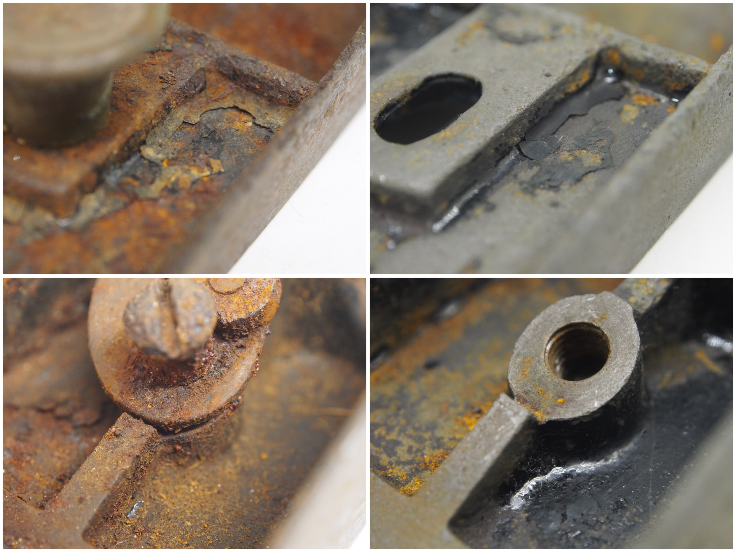
Fig 4: A close-up of the clamping mechanism

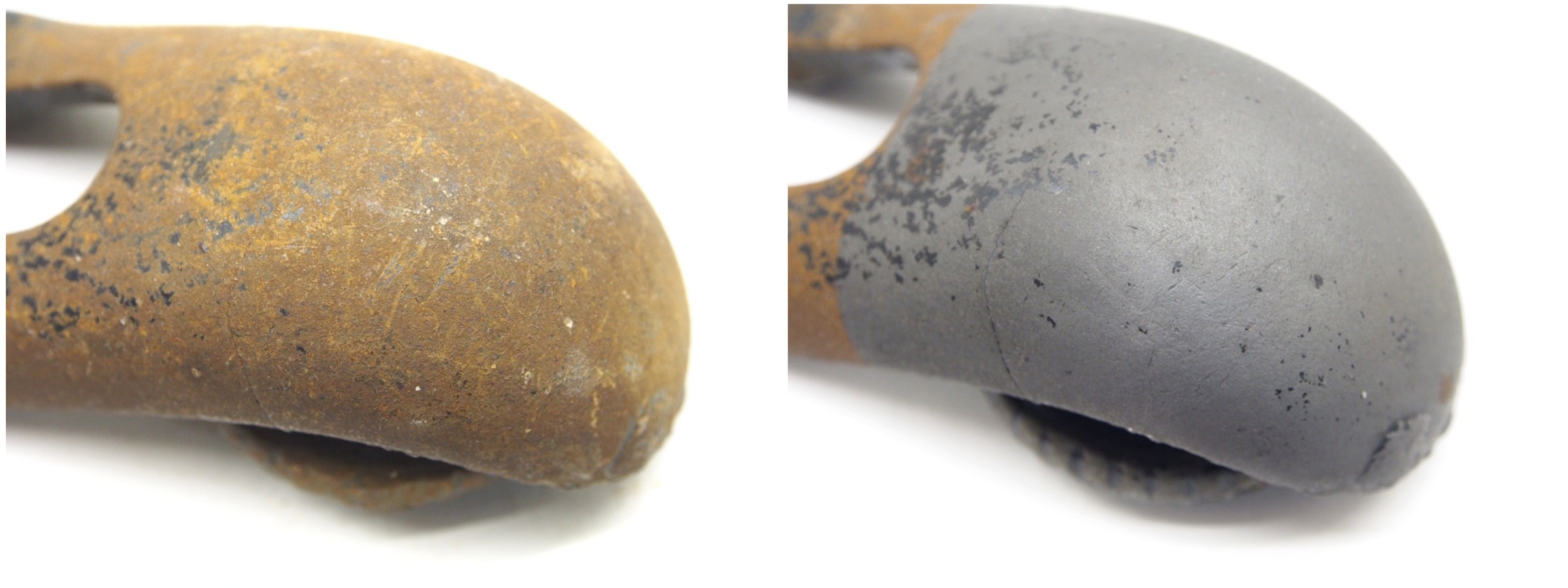
One of the issues with the original design for the knuckle lever cap was the palm rest disengaging from the cap screw. The keyhole slot in this design prevents this from happening, however to prevent the cap loosening, there is a secondary mechanism. When the lever cap is locked into place, the palm rest moves its aperture over the head of the cap screw (see photo below), so that the sides of the palm rest form what the patent terms “an annular locking shoulder engaging the abutment formed by the head of the cap screw”. Here is a view of a “Sweetheart” version of the knuckle lever cap locked in place. With this design, there was no way for the lever cap to slip once locked.

Fig.5: Sweet-heart knuckle lever cap

The interesting thing about Patent No.1,053,270 is that it outlines more than  one improvement for clamping mechanisms within the lever cap, however only one seems to have been implemented.


Evolution of the knuckle lever-cap (i)

The Stanley No.18 is one of those beautiful block planes, partially due to the polished knuckle-joint lever cap. The history of the knuckle lever-cap dates back to Patent No.355,031 issued in 1886. Invented by Samuel D. Sargent, for the Stanley Rule and Level Company, the patent was issued for improvements in “…the manner of holding the cutter bit within the stock”. More specifically, the patent was for a lever cap which can be “clamped by fewer and more direct motions“.

What Stanley proceeded to do was put the lever cap on the No.9½, and the No.15, effectively producing the No.18, and 19 planes. These planes then first appeared in the catalog of 1888. The planes had the requisite “excelsior” style rear-biased cheek.

The first version of the lever cap was comprised of two parts. The upper portion, or clamping lever,  was designed to sit in the palm of the hand, and has a two-pronged fork-like connector near the “knuckle” joint which engages the “headed screw” projecting from a threaded hole in the plane stock. Engaging the screw and pushing down on the knuckle would engage the lower portion of the lever cap, or “holding cap” (wedge). The clamping lever is connected to the holding cap by means of a pintle. When the clamping lever is depressed, the lever fulcrums on the underside of the screw head, and presses the holding-cap down upon the blade.

However, this design is severely flawed in that it usually does not engage effectively, and if the screw is not adjusted properly, can pop open.  If treated harshly, the prongs can also break off. These caps generally have the patent date “PAT. DEC.28.86” embossed on the lower portion of the lever cap. The knuckle lever was replaced with a four-piece lever cap that slips over the lever cap retaining screw, and the “spoon” portion of the lever cap then places pressure on the blade when it is snapped into place. A comparison of the two lever caps is shown below.

The original knuckle lever cap versus the redesigned version.


The Rapier pressed-steel smoothing plane

Sometimes one finds things by accident. That was the was for this Rapier pressed-steel smoothing plane. The Rapier series of planes was manufactured by the Anglo Scottish Tool Company Ltd., of Team Valley, Gateshead 11 in England. The planes produces by this company are considered to be budget planes. They generally had components that would be considered somewhat rougher than similar tools from Stanley or Record. They are generally heavier than their Stanley cousins, and usually have handles made of “shockproof plastic” (not Bakelite).

The company produced a range of bench planes (No.400 & 450 Smooth, No.500 Jack, No.600 Fore, and No.700 Jointer), block planes, and plough planes in the 1950s and 1960s. The company’ logo has a rapier in it, X, but beyond that not much is written about the company. There is a photo of the factory in Gateshead Team Valley.

The plane is a pressed steel bench plane, one of a number of these smoothing planes manufactured over the years by different companies. It has the classic Rapier red colour scheme, and nickel-plated lever cap.

The thickness of the pressed steel is 9/80″, roughly twice the thickness of the pressed steel Stanley No.104 “Liberty Bell”, which is 1/20″ (0.8/16″).

The plane is based on two UK patents : No.634,026 of March 15, 1950, and No.631,568 of Nov. 4, 1949. (it seems these are the only patents filed by the Anglo Scottish Tool Company). The plane is described  in detail in patent No.631,568:

this plane has a body which is formed from a steel pressing, in place of the more usual iron or steel casting

The plane body is constructed of two main parts: a pressed steel plane body, and a thick frog (or rather support plate) which is welded to the sides of the body. The front knob and rear handle are constructed of plastic, and attached via stems which are welded to the upper surface of the sole. The handles are attached to the stems using capping nuts. The lever cap is also constructed of pressed steel, and is nickel plated.

The lever cap, and the support plate used to rest the blade on.

Two of the most interesting aspects of this plane is the lever cap, and accompanying blade adjustment mechanism. The depth adjustment mechanism is very similar to the Norris-style adjuster. In the photographs below-left, one can see the cap iron with the plane iron fastened behind it. The plane iron has an elongated opening, which registers with the keyhole slot in the cap iron and is held in place with a bolt. This bolt is hollow to register with the pin of the blade adjustment mechanism. The photograph below-right shows the support plate, with the moveable adjustment pin projecting through the opening in the plate. The second patent No.634,026 relates to the cutting/backing iron arrangement.


The support plate

The blade adjustment mechanism provides both depth adjustment, longitudinally into and from the throat, and laterally across the throat. On the back side of the supporting plane there is a pivotally mounted block, through which passes a rotatable adjusting screw. The adjusting screw has a finger knob at the upper end to allow adjustment of the blade, and at the lower end is threaded into a nut assembly comprising a support plate, and the pin which engages with the blade/backing iron assembly. In this way, the adjusting screw can be pivoted laterally to move the blade laterally, or rotated to move the blade longitudinally.

The blade adjustment mechanism


Removing rust – the experiments (v): Evaporust epilog

As a final word on using Evaporust, here are a couple of extra experiments. The first is the lateral adjustment lever mentioned in the previous post. You can see the visual difference between the rust-free region on the left, and the rusty region on the right. This took 2-3 hours.

A rusty lateral adjustment lever

And finally, a rusty cast iron lever cap. After spending about 4 hours in the Evapo-rust, presto! rust-be-gone!

Lever cap, before (left) and after Evapo-rust


Removing rust – the experiments (iv): liquid rust removers

To test the liquid solutions, I used a series of  vintage blades with varying levels of rust – it is challenging to find four blades rusted in exactly the same way. Each blade will be submerged halfway in a rust removing liquid – vinegar, molasses, citric acid, and oxalic acid. The blades were chosen for their ingrained rust – rut that had been on the blades for years, perhaps  more than a decade (or two, or three?).

Experiment 1: Vinegar

Liquid: 250ml of white vinegar

The first experiment involved placing a blade in vinegar. I used white vinegar – although I would imagine cider vinegar would work just as well. After about an hour you can physically see the vinegar working, with small bubbles forming in the solution. The vinegar stripped the rust from the blade within 8 hours. The rust was almost lifted off the surface of the steel, forming sheets of precipitate, which slid off the blade into the base of the jar.

Vinegar seems to be extremely effective in removing rust, and leaving a very clean surface. It is also probably the cheapest form of rust removal there is, however one has to be somewhat cautious, as it is an acid, and parts left too long in the solution might experience some etching. If you look closely at this blade, there is substantial pitting, but in this case that is the long term action of the corrosion itself.

A little too much pitting perhaps?

Experiment 2:  CITRIC ACID

Liquid: 25g of powdered citric acid to 250ml of water

The citric acid also stripped the rust from the blade in under 8 hours. Unlike the rust flakes produced by the vinegar, here the rust came off the blade in small particles, and settled to the bottom of the jar.

A cautionary note here, that citric acid is corrosive, so care has to be taken when using it. This blade also had pitting, again the result of long term corrosion.

Experiment 3:  Evapo-rust

To be honest I was not going to bother with using Evapo-rust, largely because of the previous post on the Stanley No.15 rust-heap – we know it works very efficiently. However, from the perspective of speed on these plane blades, it seems like the Evapo-rust is one of the slower performers. After 48 hours there was little to no activity on the blade, and I tried a second blade in another jar – it too showed little activity in the 24 hours it was soaking. To test that I am not loosing my mind, I placed a rusty lateral adjustment lever in EvapoRust from the same container – and it actually worked (see next post). I then checked the blade from the Stanley No.16, and noticed it too had mediocre rust removal. The image below, like those previous is the original blade on the left and the post-rust removal blade right. It’s hard to effectively tell them apart. It has removed some basic surface rust.

My conclusion from this is that possibly EvapoRust does not work that convincingly on hardened steel, but works great on iron, or cast iron plane parts, e.g. bodies, lever caps, etc. Hardened steel might not be the right consistency to produce the chelating effect that Evapo-Rust relies on (ideas/comments? – I could find any info anywhere, and am yet to receive an email back from Evapo-rust Canada).

Experiment 4:  Molasses

Liquid: 50ml molasses to 250ml of water

With a ratio of 1:5  this was the slowest performing of all the liquids. I had this blade soaking for 48 hours in the molasses, after which I gave it a scrub with a scouring pad. The results are quite good, with the rust being removed from the blade. I imagine leaving it for 72 hours would be ideal.

I would say that if you had some rust that needed a long soak, that molasses may be the way to go, even with boosting the ratio to 1:4.

FINAL remarks

Below is a close-up of all four blades. I would have to conclude that the vinegar produces the best result on plane blades, and I would imagine the cheapest means of removing rust. Citric acid is a close second.

And for those interested, here is what the residue looks like for the vinegar (left) and citric acid experiments:

Vinegar vs. citric acid rust residue


Rehabilitating a Stanley No.15 (i): de-rusting (with Evaporust)

A while back I talked about identifying a block plane, that turned out to be a Stanley No.15. The plane itself is a rusted piece of trash that I bought for $1 in Maine. The first step in rehabilitating the plane is de-rusting it. Then maybe some of the seized parts will be easier to deal with. Here’s a picture of it as it looks now.

The only parts that can be removed are the lever cap and blade. The front and rear brass knobs are seized, as is the mouth plate. The lever cap is damaged, and will be replaced.

I’m going to de-rust it by dunking it into a bath of Evaporust. After the first 24 hours, I was able to remove the front thumb-rest, and the mouth plate. The rust on the sole, and two sides was also gone at this stage. After an additional 24 hours, the rust on the inner portion of the plane had been removed, and much of the Japanning. The machine screw holding the lateral adjustment lever had loosened enough to remove it (unfortunately the screw required the use of vise-grips to remove, and will have to be replaced). Here is the plane (or at least the non-damaged parts), after de-rusting.

Looking a little closer, one can see that the rust has effectively been eliminated from the front portion of the plane, with some japanning left in place. In most regions, the rust obviously formed under the japanning, and was stripped off with the chelation action of the Evapo-rust.

The frog is also in reasonablely condition.

The best way to determine how well the Evapo-rust performed is to compare regions of the plane before and after de-rusting.

Even the lateral adjustment lever has been completely stripped of rust:

Overall, the Evapo-rust performed extremely well. In the overall scheme of de-rusting a rust-bucket of a vintage plane, that cost me US$1, the outcome is tremendous. As you will notice, the rust has been converted to a gray coating over the entire body of the plane. There is also a good amount of micro-pitting on the plane body from the effects of the corrosion. However, on the upper portion of the blade, where there was more corrosion, the remaining japanning will be removed, and the plane repainted. The sole and sides have minimal pitting, and will be sanded back to produce a smooth finish.


Removing rust – the experiments (iii): oxalic acid

This one was a tricky one to run an experiment on, because the best source of oxalic acid is Bar Keeper’s Friend (BKF), which comes in liquid form, and also in powder form. BKF is an acidic cleaner used to remove rust stains from bathroom fixtures, and so is likely ideal for removing rust from metal. To test its usefulness in removing rust, I masked off a section of the sole of a rusty block plane, and made a paste of BKF powder and a little water. I then applied it to the exposed portion of the plane sole. The paste dried over a period of six hours, and to be honest, I wasn’t really expecting there to be a good result here. No doubt using BKF with a scouring pad and some elbow grease would provide some reasonable results, but just having it sit there, somehow absorbing the rust?

Well, I have to say I was intrigued after scrapping off the dried crust of BKF. The surface rust had been  removed from the sole of the plane, as is evident in the photograph.

I took this photograph without washing the de-rusted region of the sole with anything, hence the residual paste at the top and bottom. A close-up of the border between the rusted and de-rusted regions is shown below.

The oxalic acid paste really does work very well (it is stronger than vinegar), and I would recommend it for large objects that cannot be immersed in a liquid rust remover.


Why dating block planes can be difficult

Dating block planes can be challenging, more so for Stanley than other manufacturers because Stanley often changed components of their block plane, as new mechanisms appeared. It is also that Stanley’s timeline of planes is longer than most other manufacturers. Millers Falls also manufactured a whole series of block planes, but they did not appear until 1929, and were built until the early 1970s. Sargent manufactured planes from 1887 to 1964. Millers falls plane numbers were stamped into the sides of the plane, whilst Sargent often added the plane number to the markings on the blade.

Also, while exceptional type studies exist for Stanley bench planes, similar extensive ones for block planes do not. There are some exceptions to the rule, for instance, there is a type study of the Stanley No.103 block plane, and another one on the Stanley 110/120. Dating (and identifying) block planes is also more challenging than bench planes because the adjustment and holding mechanisms were often more diverse, and parts were exchangeable,  e.g. replacement of a knuckle-lever cap with a standard cam-clamp lever cap. There may also have been many changes made to the block plane throughout it’s history, for example narrowing of the blade width from 1-3/4″ to 1-5/8″, as in the case of many Sargent block planes.

Consider the ubiquitous No.9½, built from 1873 to 1973. The plane started out looking like this, the Bailey’s Patent Adjustable Block Plane:

The No.9½ in 1879: 6″ in length and a 1¾” wide blade

and morphed into this:

A contemporary No.9½: 6″ in length, a 1-5/8″ wide blade, Hand-y, and a lateral adjustment lever

Obtaining an approximate timeline involves understanding when features were added (or removed). Here are some rough guidelines (specifically for the No.9½) :

  • The Hand-y depressions on the side of the plane did not appear until 1898.
  • The lateral adjustment lever was added about 1895, unlike in bench planes where it started to appear in 1885.
  • The throat adjustment eccentric lever (patented in 1894) was not added until 1897.
  • The Excelsior design with the “hump” in the planes sides (or cheeks) biased towards the rear of the plane as opposed to the centre, disappeared around 1900.

But there is also changes in the design of the lever cap, changes in the blade depth adjustment mechanism, and markings on the plane body (e.g. foundry markings) and blades to take into account. Dating a block plane is often less of a science, and more of an art. Then of course there is always the problem of someone replacing a part on a block plane with a part from a different era.

P.S. Type studies on a series of Stanley planes can be found in John Walter’s Antique & Collectible STANLEY TOOLS Guide to Identity and Value, which has a third edition coming out in 2018.