We talk a lot about dovetails these days, but how were they perceived over a century ago? Paul Hasluck, in “The Cabinet Worker’s Handybook” (1907) describes dovetailing as “the most general form of jointing in cabinet work”. Yet while Hasluck describes the process, even mentioning puzzle and round-cornered dovetailing, he doesn’t go into specifics.
Fig.1: Examples of dovetails fromThe Cabinet Worker’s Handybook.
Below is a description on dovetail proportions and angles from a 1910 book “Modern Cabinetwork: Furniture and Fitments“, by Percy A. Wells, and John Hooper. The authors were from the Shoreditch Technical Institute, which would become the London College of Furniture.
Setting out Dovetails − The ratio between dovetail and pin varies according to the work in hand. Thus, in draw work, the pins are very narrow, and the dovetail large (Figure 3a). This makes a strong joint, and is not unsightly or cumbersome. Carcass dovetails that are concealed by plinth or cornice have the pins cut larger, the ratio of pin and dovetail being 1:3 (Figure 3b). Cistern dovetailing required to resist the heat generated when soldering the lead lining, have both pin and dovetail equal, any shrinkage which may then occur is evenly distributed throughout the whole case (Figure 3c).
Angle of Dovetails − The angle for cutting dovetails to obtain the maximum amount of strength from the joint may be either 1 in 6 (9.5°) or 1 in 8 (7.1°). It will be found advantageous to cut exterior dovetailing, such as drawers, instrument cases etc. where they must have a neat appearance, 1 in 8, and the heavier types of carcasses, bases, and chests, 1 in 6.
Many woodworking instruction books of the period did not specify an angle as such, or suggested that the angle of the sides of the “tail” should not exceed about 15°, for hardwoods a little more, and soft, weak woods as little as 10° [1] (note that many older texts specified angle from 75-80°, see the Figure 2). A 1 in 4 dovetail has an angle of about 14°.
Fig.2: Different ways that dovetail angles are expressed
Fig.3: Different dovetail spacing
Bernard Edward Jones, Every Boy his Own Mechanic (1919)
So with some background on Japanese saws, which one should you choose? Like Western saws, some are better at some tasks than others, but there are likely more types of saws than in Western woodworking. Now let’s consider some of the differing types of Japanese saws. There are a number of different forms of saws, some of which are for rough cuts and dimensioning lumber, some of which are for construction, and others for fine cabinetmaking. Toshio Ōdate discusses most of these in his book. The saws described below are perhaps those most commonly used in Japanese woodworking (at least in a Western context).
First there are the Ryoba, which apart from being a style of saw, is a term used in the context of a specific genre of saws. Basically when companies describe a saw as a Ryoba, they mean a two-edged saw with one edge crosscut and the other edge rip.
Ryoba
These saws are suitable for everything from rough carpentry (dimensioning or re-sawing wood) to fine furniture. In many ways Ryoba saws are the equivalent of western rip and crosscut panel saws. Ryoba are generally used with two hands, and the saw is held at a steeper angle for an easy cut, of a low angle to gain more control.
Name: Ryoba - dual purpose, with two cutting edges
Style: Ryoba
Teeth: cross-cut and rip
Suitability: deep, rough cuts, dimensioning wood
Blade length: 20-36cm
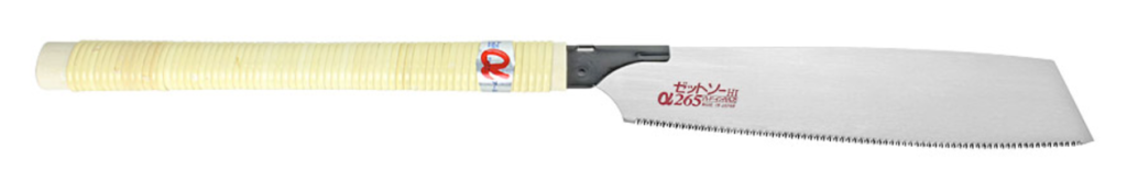
The largest category of saws is likely the single-edged Kataba style saws that are not Dozuki. The blades on these saws do not have a spine, and come in various different forms, with crosscut, rip and hybrid teeth.
Kataba
Name: Kataba - dual purpose, with a single cutting edge
Style: Kataba
Teeth: cross-cut and rip
Suitability: working cuts, dimensioning wood
Blade length: variable cm
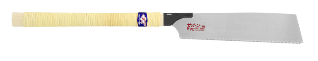
The Dozuki or Douzukinoko is a single edged saw suited to fine detail work. These saws have a very thin blade which is supported by a steel or brass spine. The teeth are very fine (typically 24 tpi), and have very little set, and the saw leaves an incredibly smooth surface. One limitation of course is that the depth of cut is limited by the spine. Most are crosscut, but Dozuki rip saws exist as well.
There is one issue in that the saw typically used by Westerners to cut dovetails is the Dozuki which is a cross-cut saw, however cutting dovetails is a ripping operation.
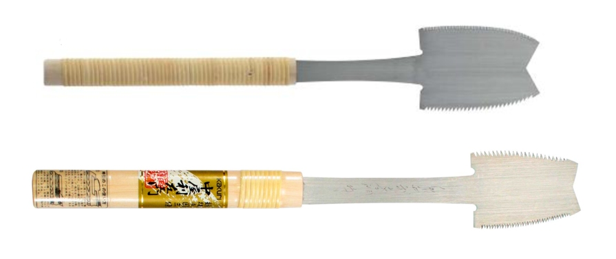
The Azebiki can be single or double-sided, and has a curved blade that allows a cut to be started or stopped in the middle of a board. The blade is usually quite short, and therefore requires a guide block. These saws are exceptional for cutting things like sliding dovetails.
Azebiki
Name: Azebiki - short blade, curved edges + long neck
Style: Kabata and ryoba
Teeth: cross-cut or rip
Suitability: starting centred cuts, sliding dovetail joints
Blade length: short
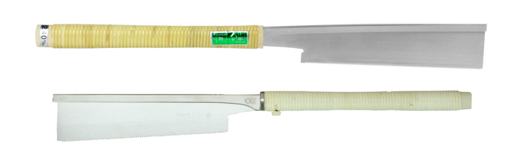
The Kugihiki is a flush cut saw used for dowels or trim.
Kugihiki
Name: Kugihiki - flexible blade, no teeth set
Style: Kabata and ryoba
Teeth: cross-cut
Suitability: flush cutting dowels
Blade length: 18-20cm
Anahiki saws typically have a curved blade. Prior to industrial times, saws with curved blades were quite common, which is likely because the back and forth movement of the human arm tends to trace a curve rather than a straight line and this curve will be followed by a saw. Today it is easier to produce straight lines rather than curved ones, so they have fallen out of favour.
Anahiki
Name: Anahiki - long blade, rough work
Style: Mostly kabata
Teeth: cross-cut
Suitability: large timbers and beams
Blade length: 31-46cm
A commonly overlooked but very useful saw is the Mawashibiki, keyhole saw for cutting a curved or circular hole. The blade is usually tapered from front to back and top to bottom. The blade is typically made of softer steel to allow for more flexibility.
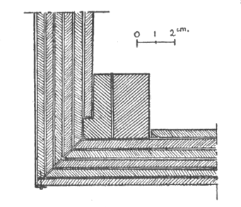
We think of plywood as a modern invention, but is it? it is surprising to learn that the ancient Egyptians were already using plywood. In the 1933 edition of Annales du Service des Antiquités, there is a description of a coffin whose walls, and bottom were made of plywood, found at Saqqara and dating from the Old Kingdom (ca. 2700–2200 BC). There are six layers of wood, each 4mm in thickness, placed with the grain alternating in each direction [1,2], just as you would find in modern plywood. The first layer of the interior side made of vertical boards, and the outer layer of horizontal boards. The boards were anywhere from 4-30cm in width, yet none of the pieces of wood was broad enough for the height of the sides, or long enough for the length of the coffin [3].
Fig.1: Diagram of the plywood from [2, p.164] showing the side and bottom layers of plywood joining.
Fig.2: Layers of wood forming the bottom of the coffin.
In certain places on the boards there are small holes, generally paired, which pass through all layers of the plywood, intended to help bind them together. Between boards of the same layer, connection was ensured using small independent tenons engaged and dowelled in corresponding mortises made in the thickness of each board. The joints of the boards a the corners of the body were reinforced with wooden sticks. Due to the scarcity of large wood pieces, it seems the ancient Egyptian carpenters were very skilled at the technique of “patchwork” construction, joining irregular pieces of wood “by means of flat tongues or dowels, butterfly cramps, various forms of lashing and pegging, and sometimes in fine work by tongue and groove.” [3].
Further reading
Eric Marx, “Ancient Egyptian Woodworking”, Antiquity, 20, pp.127-133 (1946)
Annales du Service des Antiquités, (1933)
D.M. Dixon, “Timber in Ancient Egypt”, The Commonwealth Forestry Review, 53(3), pp.205-209 (1974)
If you grew up in the 1980s, or before, you likely remember a time when kids were allowed to take risks, I mean our whole childhood seemed to involve a risk of one sort or another. I remember being able to buy potassium permanganate (from a chemist in Australia, the equivalent of a pharmacy), and adding a second ingredient to make it spontaneously combust. We use to carry knives when camping, and learned very early the dangers of fire. Yet we played with all these things and survived. I don’t ever remember anyone getting majorly injured, and if they did, they lived with whatever scars they had… most of which we patched up with some disinfectant and a band-aid. If someone broke their arm acting stupid on a play structure, they didn’t seal off the play structure. People that grew up in the atomic era of the 1950s had it even riskier – dangerous toys like chemistry sets, physics sets with real uranium samples, and rocket kits.
Fun and dangerous toys?
A recent article on this subject talked about letting kids take risks… including “supervised play involving tools, like using an axe and hammer to build a fort”. But instead some parents continue to dump their kids in front of a screen of some sort – I mean it’s easy right? Kids use to be outside, building forts, climbing trees, and damming creeks. These days when you walk through a neighbourhood there are few if any kids outside. There are ravines close by to where I live, which in the 1970s I imagine would have been filled with kids in the summer… today they are mostly empty. Sure the difference is that anyone born before 1980 had to amuse themselves as kids. The adage “children should be seen and not heard” rang true, although I kinda believe it was more “children should be neither seen nor heard”, at least until dinner time (when they could be seen).
Stanley Tool Chest No.904½
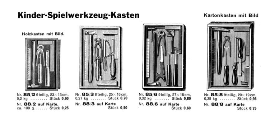
Children’s play-tools from Bonumwerke Tigges & Winckel (Germany, 1935)
Look, I’m not advocating for dangerous toys, but iPads and gaming platforms likely do more damage to young people than any of the 1950s toys ever did. What we have managed to do is raise a couple of generations of kids that have no perceived skills with tools, few ideas about building things – whether that be tools in the kitchen, in the workshop, or outdoors (Lego sets are not really that imaginative these days, they really are just follow-the-instruction type toys), and little in the way of problem solving skills. Hammers are not dangerous, if kids are taught to use them properly, and that’s the key here, learning to use them properly. Already in the 1930s it wasn’t unusual for tool companies to sell “children’s tool kits”.
Building models from scratch or using building kits?
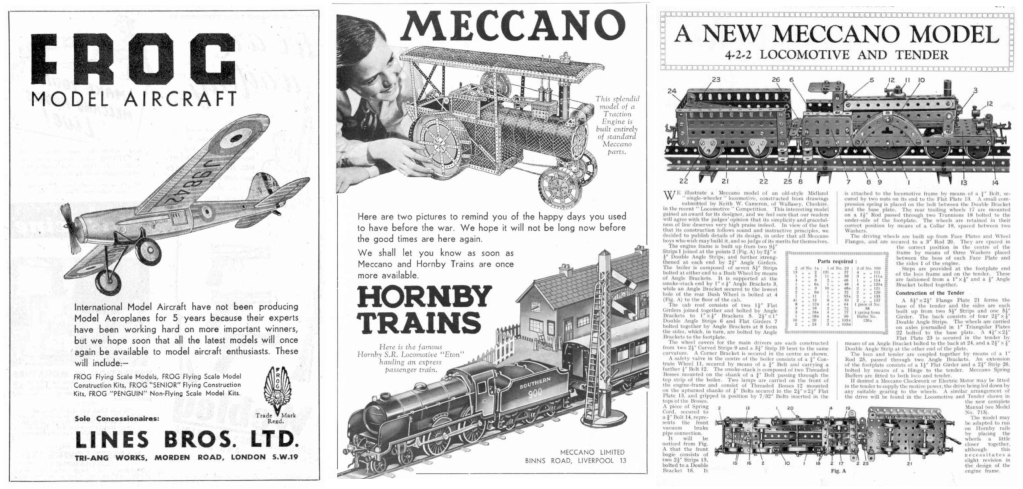
But it isn’t even woodworking tools. Kids from bygone eras built models, like ships, or aircraft, and whole model railroad systems, fromscratch. There were magazines dedicated to building things, like the British magazine (and store) Hobbies, and systems of building like Meccano, Minibrix, or Fischer-Technik. That is to say there were also methods of learning to build things that didn’t involve axes and chisels. Meccano Magazine for instance included articles on building things with Meccano, but also articles on engineering things, and new concepts in transportation, aircraft, building.
You had to teach yourself basic tool skills, because if you wanted a go-cart, you had to build one yourself. Maybe you got hold of some lawnmower wheels, and salvaged some lumber from the neighbourhood somewhere, but basically you had to build the thing yourself. All these skills, often self-taught boosted your problem-solving abilities, and likely had an impact on developing fine motor skills as well.
The bottom line is that we have somehow concluded that all these skills can be learned in a virtual digital realm, and that just isn’t true. Because what we end up with is people who grow up with few if any real skills, i.e. they can’t even use a hammer, all because parents (and schools) feel like everything is too dangerous. Again, I’m not advocating for kids to walk around with pocket-knives, and whittling branches in the school yard, sadly those days are gone. But what about advocating for more summer camps where kids can learn some basic tool skills? It is time to pop the bubble-wrap and let kids actually learn to play with tools and build things.
Dowels may be becoming in more vogue again, but what about their strength? The problem with deciding whether one fastener is better than another is that fact that it is a fairly broad thing to test. It has to do with many differing factors: the diameter, length, and species of the dowel, the type of adhesive used, and or course the characteristics of wood being joined.
Most of the explorations into dowel strength have compared them to other joints using simple tests of joint failure. A good example is this experiment from Canadian Woodworking from 2010. They tested a T joint in solid oak by comparing: (i) a 3-dowel joint (⅜”×2″), (ii) a mortise and tenon joint, and (ii) a 2-biscuit joint. The biscuit failed at 325lbs of force, the M&T at 500lb, and the dowel-joint at 650lbs. An article, “Joint Success” in British magazine Furniture & Cabinetmaking showed the following failures (tested using a hand-pump hydraulic ram) is shown in the table below. None of the fixings failed.
Method
Specs
failure (psi)
What failed?
biscuit joint
1 × No.20
180
glue line + fracture of material parallel to biscuit slot
Dowelmax
5 × 10×50mm dowels
660
glue line
Domino
2 × 8×40mm tenons
400
glue line + partial fracturing along the grain
mortise and tenon
45mm depth
420
glue line
pocket hole
280
screw and glue line
Furniture & Cabinetmaking
Yet another test from the November 2006 issue of Wood Magazine “Wood Joint Torture test”.
Method
Shear test (lbs)
Pull-apart test (lbs)
mortise and tenon
1017
2525
Dowelmax
609
1866
Beadlock
541
1486
Domino
464
1170
biscuits
187
766
Wood Magazine (2006)
The reality is that actual testing of joints would likely have to include the use of different species of wood for dowels, the use of various glues, and the application to various types of connections, and target species. It would require a large study that also assessed the effect adhesive curing has on the strength of a joint. There is actually a load of commercial research into the area of fastener strength, which isn’t really that surprising. This is partially because it is the most commonly used joint in commercial furniture construction (largely due to the fact that it is inexpensive). With the resurgence of interest in multi-storey wooden buildings, there will no doubt be more interest in the use of dowels in timber engineering. Below are some examples of dowel strength in the literature.
In a 2022 article from the Warsaw University of Life Sciences [1], the authors investigated the influence of the type of invisible wooden connectors on the strength in glued corner joints for chipboard and MDF, which are commonly used in the construction of box furniture. They used (i) four wood grooved beech dowels, (ii) two beech Domino tenons, and (iii) a mixed arrangement of connectors. Results showed that dowels provided the highest strength over Domino tenons. They also determined that the use of MDF over chipboard increased the strength.
Many studies look at withdrawal strength, which isn’t exactly the sort of strength tests you see in peoples workshops. A 2020 study [2] looks at the withdrawal strength of 8mm plain and spiral dowels made of beech and oak. The authors investigated the influence of relative humidity, dowel structure and wood species on withdrawal strength. Spiral dowels were found to have a significantly higher withdrawal strength over plain dowels. The influence of the wood species was not found to be statistically significant overall.
Another study [4] looked at the joints made from hardwood plywood of 19 mm thickness, using beech and hornbeam multi-grove dowels in various diameters (6, 8 and 10 mm) and depths of penetration (9, 13 and 17 mm). The best results were for joints made with 8mm beech dowels penetrating 17mm into the joints. The 10mm diameter dowels failed, likely due to reduced edge thickness in the panels. In general strength does increase with dowel diameter. There are even studies which look at optimal dowel spacing. In one study [5] the author found that the optimal spacing of dowels in cabinet construction (MDF and particleboard) was 96mm. Spacings of 32mm and 64mm resulted in a reduction of the maximum load-bearing capacity per dowel due to over-lapping zones of influence by neighbouring dowels.
There are even studies that look at structural joints made with axially loaded glued-in hardwood dowels [3]. The authors of one study [3] look at various large plywood (Glulam) beam configurations held together with a series of 12mm by 120mm dowels. Withdrawal strength was found to be about 30 MPa (4351 psi), and overall joints have high strength properties (except the dowel joints do succumb to brittle shear failure of adhesives or wood members).
In all likelihood, dowels are a very good choice for holding together a joint in a piece of furniture. I mean in normal furniture there is never really going to be the excess loading applied in testing. You just have to make the appropriate choice for the material being used. For most circumstances, that’s likely a ⅜” diameter spiral dowel, made of a species like beech. It may be even possible to use them to join larger structures such as workbench bases, where multiple ½” diameter dowels, 3-4 inches in length could be used.
Further reading
ŚMIETAŃSKA, K., MIELCZAREK, M., “Strength properties of furniture corner joints constructed with different wooden connectors and wood-based materials”, Ann. WULS – SGGW, Forestry and Wood Technology, 118, pp.55-66 (2022)
Podlena, M., Böhm, M., Hýsek, S., Procházka, J., Černý, R., “Evaluation of Parameters Influencing the Withdrawal Strength of Oak and Beech Dowels”, BioResources, 15(1), pp.1665-1677 (2020)
Koizumi, A., Jensen, J.L., Sasaki, T., “Structural joints with glued-in hardwood dowels”, Joints in Timber Structures, pp.403-412 (2001)
Dalvand, M., Ebrahimi, G., Tajvidi, M., Layeghi, M., “Bending moment resistance of dowel corner joints in case-type furniture under diagonal compression load”, Journal of Forestry Research, 25, pp.981-984 (2014)
Tankut, A.N., “Optimum dowel spacing for corner joints in 32-mm cabinet construction”, Forest Products Journal, 55(12), pp.100-104 (2005)
The Germans really were never into metal planes, although it seems that some companies did flirt with the idea, more for hobbyists than real woodworkers though. These planes came from the 1935 catalog of German tool company Bonumwerke, Tigges & Winckel K.-G.. Founded in 1860 by Robert Tigges in Dörfchen Cronenberg, it primarily produced steel stamps. In 1869 the company moved to Remscheid-Hölterfeld and production was expanded to include tools for plasterers, sculptors and gold workers. The Bonumwerke had been based in Langenberg since around 1920.
The BONUM planes
The “Amerikanischer art” metal plane was meant to mimic American metal planes. It came in three variants: the 2100 (120mm long), the 2101 (160mm) and the 2102 (210mm). This is basically a pressed metal plane with wooden blocks for handles, almost like a poor-man’s infill plane – like super cheap to make for those who wanted to “experience” the American plane. The second plane was made for hobbyists, and also came in three variants: No.805 (100mm without nose), No.806 (100mm), and No.807 (140mm). This is essentially a type of block plane, but made entirely of pressed steel. It almost has the feeling of a modern RALI.